Intro
An ADS Interface is a diagnostic interface for older BMWs. Last 20-something years I'm crazy about old BMW, especially older "cult" models such was E30, E32 and E34. Luckily, I was able to afford a cheap '87 BMW E30 in my young days, and the love stick with me for years after.
Now, almost 10 years later, I drive an E34 520i '94 which was my dream car ever since I was a kid. The thing with these cars is they are old. Like really, old. As much as I am, if not more. I feel cranky in my late twenties, so I suspect those cars feel even worse. And with an old car, comes an obsolete protocols and technical informations not useable today. This ADS Interface is rarely to be found, as the protocol is proprietary.
What are we working on
Today, I wanted to present a small electronic project I've been building, presented on bimmerforums.com sometimes in 2011. The project is revolving around old ADS interface that BMW used for diagnostic, way before OBD standards were eventually planned and implemented.
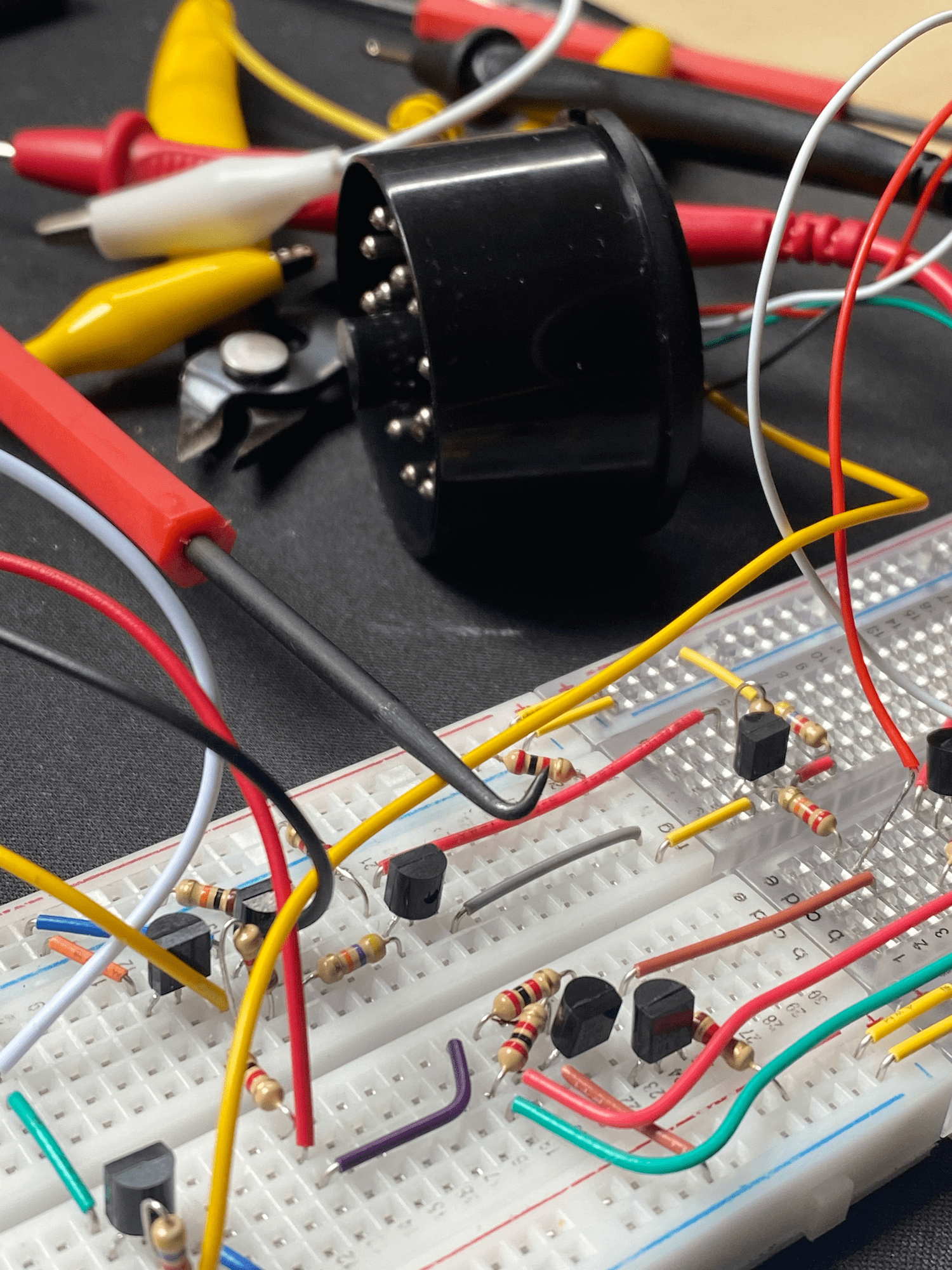
The target for the final project will be this beauty:

For a good start, reading upon KeyWord-71 protocol (KW-71) standards is a huge boost. The standard was implemented on diagnostic tools with electronic blocks BMW cars produced before 1995 includes E30 (Series 3), E32 (Series 7), E34 (Series 5). The physical implementation is based on the interaction of two lines called K and L, described as K-Line which produces bidirectional data, and L-Line which handles unidirectional data.
Building
I browsed the forums here and there and collected all necessary details and electronic components to start building the project and comparing my final build against known details. Sort of a research work for a beginner in electronics such as me.
What I needed was a couple of resistors of different resistance, some transistors which I suspect act as a gates in the voltage delivery/control flow, and two I/O interfaces, on one side a typical BMW 20-pin diagnostic port (for which only few pins are used), and a serial interface RS-232 for delivering the signal updates on a PC. If you are wondering why is RS-232 implemented here; is because the K and L lines described above are compatible with this protocol, therefore the implementation corresponds to logical signals of the DS.
Below is a schematic of the final build, laid down on a PCB or breadboard.
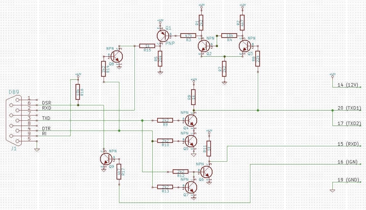
Although it doesn't look that hard to build, the conjunction lines are making this project a bit tedious for beginners, especially in regards to N/P transistors and their orientation. On the left side, there is a serial interface that acts as an output point in the control flow. on the right is a BMW diagnostic input that acts as a K/L-Line. In the middle, there are couple of resistors and transistors that acts as a logic gates, creating different IO understanding of the signals. Most notable pins are TXD and RXD, while the other three are 12V as a power (14), Contact pin (16), and Ground (19).
It is important to note that pin 20 and 17 are shorted from the BMW I/O. Respectively, they are delivering the signal from the shorter route.
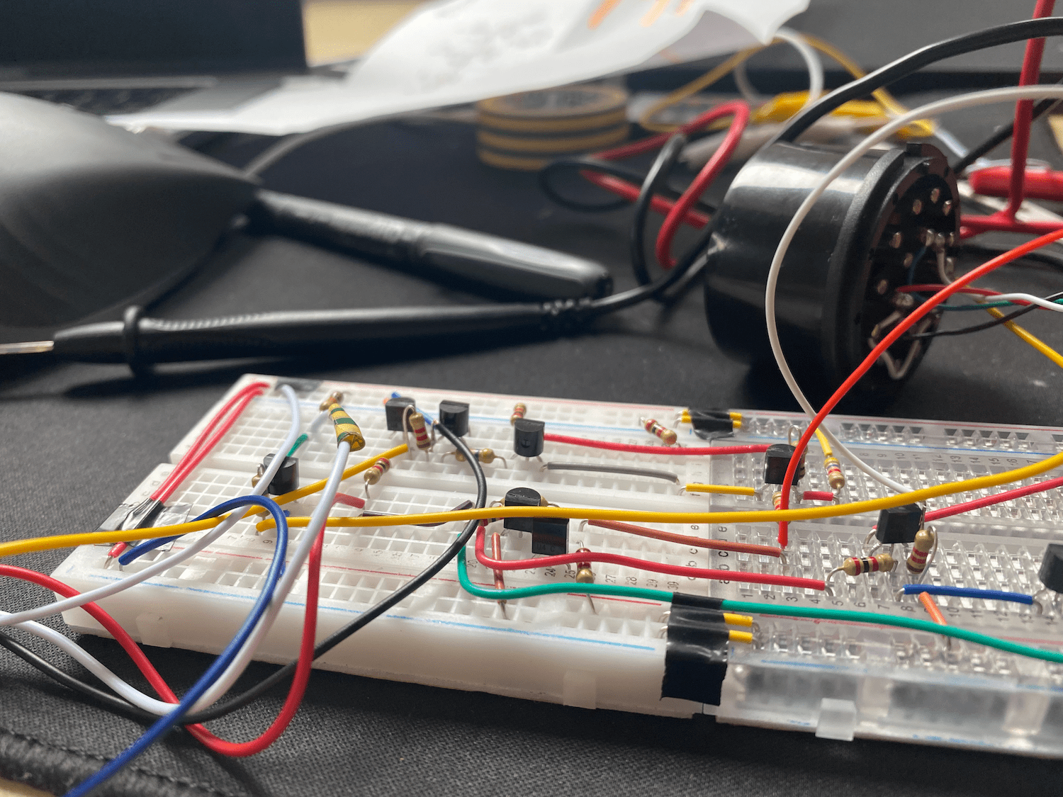
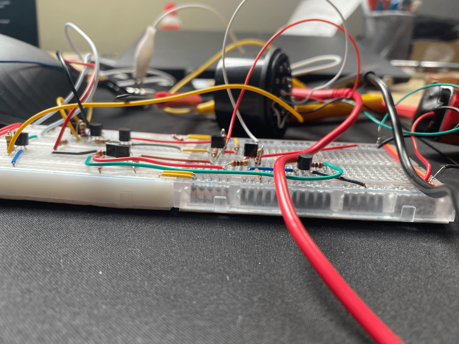
Because I wanted to build a rather "readable" breadboard project for the final QA, I connected two medium sized breadboards and connected their power rails to deliver full IO through it.
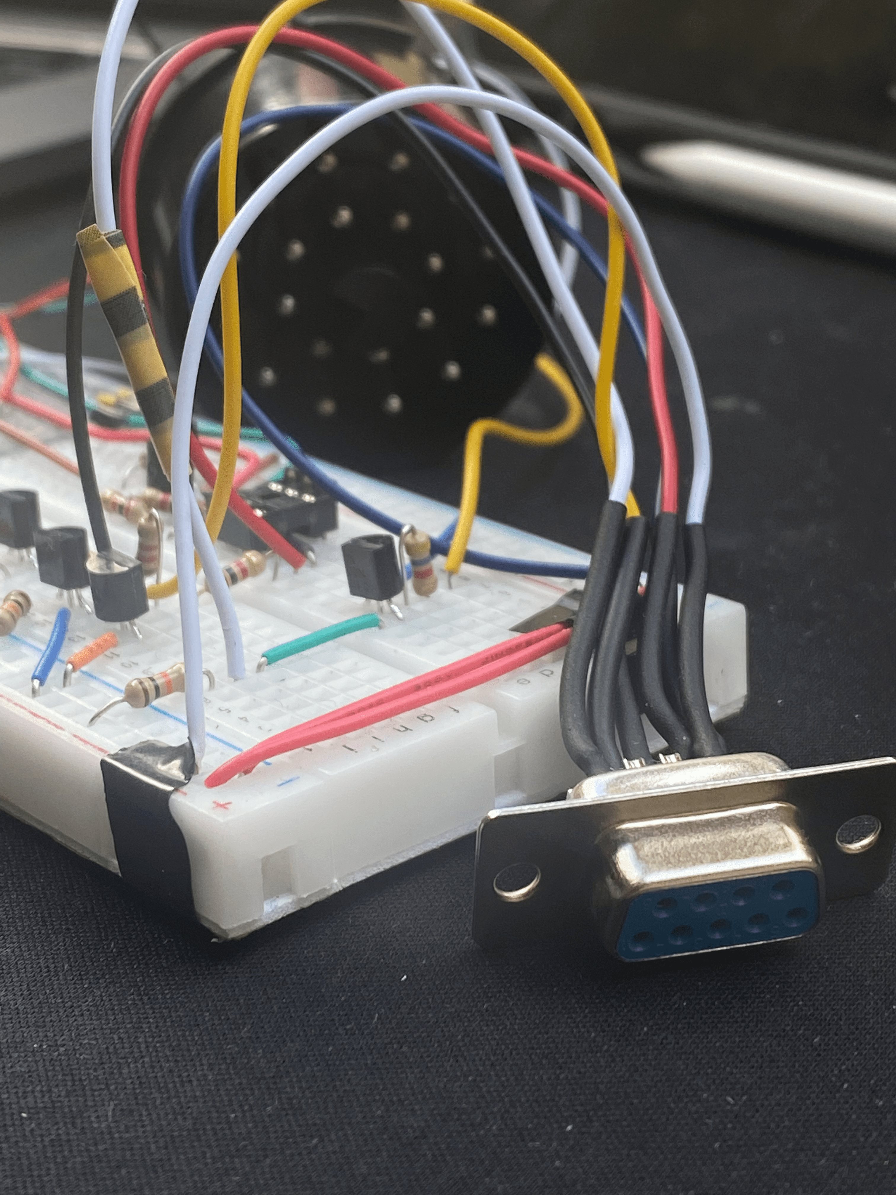
Final Result
After assembling the components on a breadboard, and comparing it against schema, I started beautifying the board by cutting all components legs to appropriate size, and replacing jump wires with the breadboard wires. The jump wires comes handy when you are prototyping the board but as this project will be used in a rather harsh environment, such is a car garage, I wanted to make sure it will stay as-is during the intended operations.
QA and Outro
So long, the journey ends. It took me a couple of tries to successfully build it. For a quick testing, I've used multimeter and a 12V battery attached on power rail via the pin 14. Testing resistance at different points was the easiest part. The hardest part was a final quality assurance which I did with couple of persons whom I want to credit here: s0cket, and Emir T.; both of them a good friends doing electrical engineering. Additionally, a huge thanks to @benemorius from bimmerforums.com for reverse engineering the protocol for us.

Part List
8x 2n3904 NPN switching transistor
1x 2n3906 PNP switching transistor

7x 2.2 kOhm resistor
2x 4.7 kOhm resistor
1x 47 kOhm resistor
2x 10 kOhm resistor
1x 20 kOhm resistor
1x 22 kOhm resistor
3x 1 kOhm resistor